Transparent Concrete
Transparent Concrete
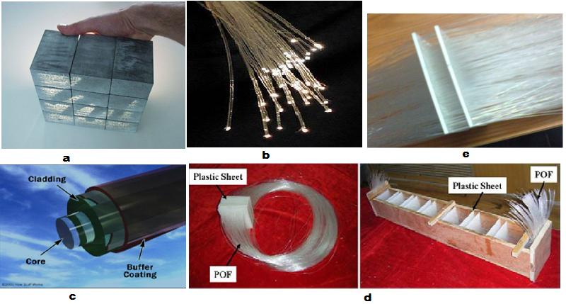
Transparent concrete was first developed in 2001 by Hungarian architect Aron Losonczi at the Technical University of Budapest. The translucent concrete comes in precast blocks of different sizes. In Light-transmitting concrete, which is also known as translucent concrete, optical fibre’s strands are cast into the concrete to transmit light, by either naturally or artificially through translucent panels. This material can be used in a wide range of architectural and interior design applications, including cladding and dividers. The fibers in the concrete run parallel to one another, Transmitting light between the two surfaces of the concrete component in which they are embedded. Optical fibers transmit light so efficiently that there is almost no loss of light conducted through the fibers.The concrete mixture is made up of fine materials only i.e. it contains no coarse aggregate (CA). To make translucent concrete, Fiber Optic Glass are needed.Polishing is then has to be done to the surface to allow the fibers appears and let the light passes from one side of the fiber to the other side. Fig 1-a shows a typical sample of a Light-transmitting concrete.
PRINCIPLE OF OPERATION
Optical fibers generally work as a hollow cylindrical wave guide which transmits light along its axis, by the principle of total internal reflection as shown in Fig 1-b, the optical fiber strands.
Parts of Optical Fibers
- Core – It is thin glass center of the fiber in which the light travels.
- Cladding – It is the outer optical material surrounding the core which reflects the light back into the core.
To lock up the reflection in the core, refractive index of the core must be more than that of the cladding.
- Coating – It is the plastic coating which protects the fibers from damage and moisture.
Fig 1-c shows the different parts of optical fibers while Fig 1-d shows the configuration of the smart transparent concrete.
Table-1 shows the different properties of transparent concre
| Properties of Transparent Concrete Specimens by Litracon Company Product | Translucent Concrete |
| Form | Prefabricated |
| Ingredients | 96% concrete, 4% optical fiber |
| Density | 2100-2400 Kg/m 2 |
| Block size | 600 x 300mm |
| Thickness | 25-500mm |
| Colour | White, Grey or Black |
| Fiber distribution | Organic |
| Finished | Polished |
| Compressive strength | 50 N/mm 2 |
| Bending Tensile strength | 7 N/mm 2 |
FABRICATION AND ANALYSIS OF LIGHT TRANSMITTING CONCRETE
This section discusses the different materials used in producing light transmitting concrete with its specifications. For the present study, glass rods and optical fibers were used for making the concrete translucent. The specimen dimension of the sample produced using glass rods and optical fibers were 150 x 150 x 150 mm cube and 150×100 x 100 mm cuboid respectively. Table 2 below shows the specimen dimensions for glass rods and optical fibers and Table 3 gives the specifications of material used in preparing the light transmitting concrete.
Table- 2 Specimen dimensions
| Sl.No | Specimen Type | Specimen Dimensions |
| 1. | Glass Rods | 150 x 150 x 150 mm cube |
| 2. | Optical Fibers | 150×100 x 100 mm cuboid |
Table- 3 Material specifications
| Sl.No | Material | Specifications |
| 1. | Cement | 53 Grade |
| 2. | Aggregates | 4 mm Down Size
( Only For Glass Samples) |
| 3. | Sand | 2.36 mm Sieve Passing |
| 4. | Glass Rods | 0.5 mm Diameter Rods |
| 5. | Optical Fibers | 200 μ Diameter Strands |
| 6. | Concrete | 1.0 : 1.5 : 3.0 |
| 7. | Cement | 1.0 : 2.0 |
| 8. | W/C Ratio | 0.5 – For Glass Samples.
0.45– For Optical Fiber Samples. |
-
MOULD AND SPECIMEN FABRICATION
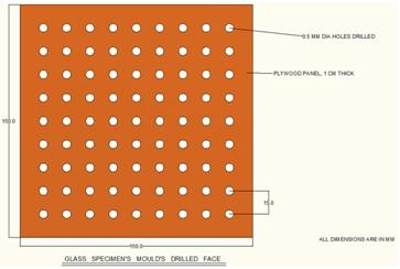
1. Glass rods: – The glass samples to be fabricated are of size 150x150x150 mm cube. The mould is made up of two steel faces and two plywood faces with a steel base plate. The two faces of plywood are drilled at a uniform spacing of 1.5 cm to hold the glass rods in place during casting concrete into the mould as shown in Fig
- All the side faces, two of drilled plywood and the remaining two of steel plates, are bolted down to a steel base plate. The two drilled plywood faces are placed opposite to each other so as to orient the glass rods in a single direction.
The glass rods are cut into sufficient length and placed individually through the holes in the two plywood sides facing opposite to each other. Now the concrete is prepared in 1.0:1.5: 3.0 proportion and poured into the mould. The mould is agitated with the help of mechanical vibrator so as to avoid improper filling and void formation. The sample is then allowed to harden for 24 hours and then the mould is removed and the sample is kept for curing.
Optical fibers: – The samples containing optical fibers fabricated are of size 150x100x100 mm cuboids. The mould is made up of two plywood side 100×100 mm facing each other and the other two sides are Printed Circuit Boards (PCB) 150×100 mm which is used to make electronic circuit boards as shown in Fig 7. They are perforated boards and the sides are rested on a plywood base. The optical fiber strands, batched by volume (or fiber to cement ratio), are placed through the holes individually. The cement paste is then prepared in 1.0: 2.0 proportions and poured into the mould and agitated with the help of mechanical vibrator to avoid void formation.
- EXPERIMENTAL PROGRAM
The samples for light transmitting concrete were prepared by varying the spacing of glass rods and optical fibers keeping minimum spacing for optical fibers equal to the spacing of perforations in the PCB. The various tests were then conducted such as light transmitting and compressive strength test as discussed below.
Light Transmittance Test On Specimen
Light measuring equipment and setup
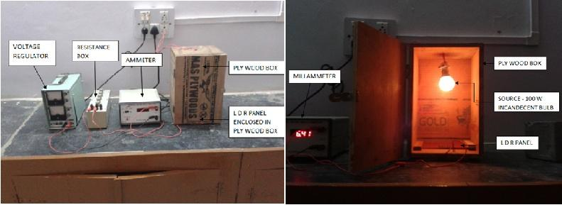
Various light measuring equipments is available such as Lux meter, however, a simple Lux meter can be made in a laboratory using simple components [6]. The light transmittance through the sample can be measured by measuring the current corresponding to the light which can be measured by a photo diode or a Light Dependent Resistors (LDR). The use of photo diode would require a separate sensor which would increase the cost of the project. The most apt choice would be LDR. The LDR are soldered onto a PCB board as shown in figure4 below. The experimental set up is as shown below in figure 5.
As shown in the above figure 5the LDR measures the light transmitted through the sample and converts it into the current, which in this case is measured in mili amperes (mA). So two readings are taken, one without sample (A1) and one with sample (A2). The source of light here is taken as 100 w incandescent bulbs, a resistance of 100 Ω is applied in the circuit and a uniform DC voltage of 2.5 V is kept between the circuits. To ensure no light escapes throughout the test, a box made up of plywood (as shown in figure) is made. The light source is fixed at the top of the box and LDR is placed at the bottom. The sample is placed between source and LDR and test is carried out. The circuit arrangement of the experiment is shown in figure 6.
Figure 6: Circuit arrangement of experiment
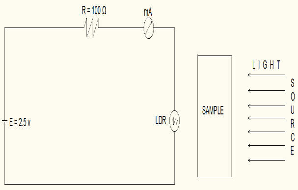
Table 4 Test results for light transmission
| Samples | Glass Specimen | Optical Fiber Specimen | ||||
| Area
( mm 2) |
1.5 cm
spacing |
3.0 cm
spacing |
4.5 cm
spacing |
0.5 cm
spacing |
1.0 cm
spacing |
2.0 cm
spacing |
| Ammeter
Readings ( Ma ) |
14.42 | 14.42 | 14.42 | 14.42 | 14.42 | 14.42 |
| 0.226 | 0.113 | 0.036 | 1.37 | 1.21 | 1.07 | |
| Light Transmittance
100 – A1−A2 ______ *100 A1
|
1.57 | 0.785 | 0.254 | 9.5 | 8.39 | 7.41 |
Compressive Strength
The compressive strength of samples was then determined after measuring the light transmitted by using compressive testing machines and test results were obtained as given in Table 5. As it can be seen from Table 5 the compressive strength of Light Transmitting Concrete was found to be ranging between 20 – 23 N/mm 2 with optical fiber specimen and with glass rods specimen the compressive strength was found to be ranging between 24-26 N/mm 2 , which indicates that the concrete satisfies the compressive strength requirement for M 20 grade concrete.
Table 5- Test results for the sample.
| Samples | Glass Specimen | Optical Fiber Specimen | ||||
| Area ( mm 2 ) | 150 x 150 | 150 x 100 | ||||
| Spacing of rod/strand | 1.5 cm | 3.0 cm | 4.5 cm | 0.5 cm | 1.0 cm | 2.0 cm |
| Compressive Strength (N/mm 2 ) | 24.57 | 25.1 | 25.27 | 22.2 | 21.3 | 20.7 |
-
CONCLUSION
After the experimental investigation, following conclusions can be made. The compressive strength of Light Transmitting Concrete was found to be ranging between 20 – 23 N/mm 2 with optical fiber specimen and with glass rods specimen the compressive strength was found to be rangingbetween 24-26 N/mm 2 , which indicates that the concrete satisfies the compressive strength requirement for M 20 grade concrete. Light transmittance for the samples was found to be 7.0 to 10.0 % for optical fiber specimen and 0.2 to 1.50 % for glass rod specimens. The transparency of concrete specimens with glass fibers is more as compared to the specimens with glass rods and also justifies the fact that more the transparency of the material more effective will be the light transmittance.
Thus the study concludes that the transparency of light is possible in concrete without affecting its compressive strength, as the optical fibers and glass rods act as fiber reinforcement thereby enhancing the strength and also enhances appearance.
Hi
I am Phd Student.
I research about waterproofing concrete crack.
For watching the manner of injection in crack or using waterproofing coating, I need to build transparent concrete. Can you help me how can I produce it ?
I read that is soo expensive, Am I right?
Any good references about this type of concrete?